
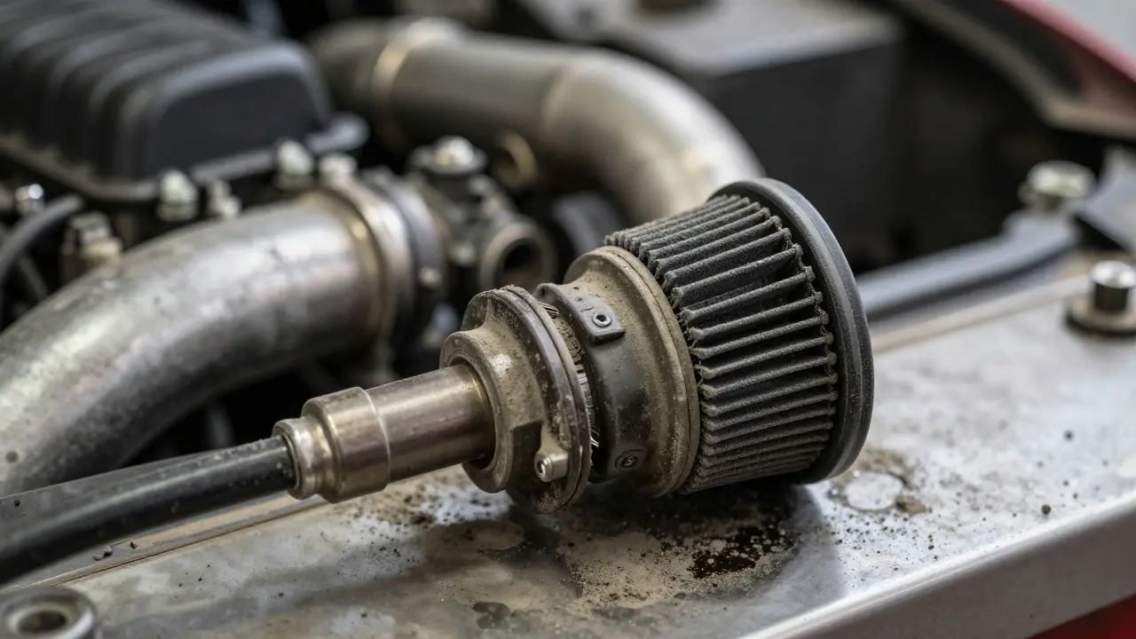
You’ve got a modified engine sitting on the dyno, or maybe just idling in your garage, and you’re staring at a data log that makes no sense. The air-fuel ratio is dancing all over the place. You suspect the sensor isn’t reading right, but which one? Is it the Mass Air Flow (MAF) sensor that’s dirty, or is your Speed Density system struggling with incorrect volumetric efficiency tables?
This isn’t just a theoretical debate for car enthusiasts anymore. It’s the fundamental choice between two distinct philosophies of how an engine control unit (ECU) decides how much fuel to inject. One measures what goes in; the other calculates what *should* go in based on pressure and temperature. Getting this wrong means poor performance, rough idles, or worse, melted pistons. Let’s break down exactly how these systems work, why tuners are increasingly ditching MAFs, and which strategy actually suits your specific build.
How Mass Air Flow (MAF) Tuning Works
Think of a MAF sensor as a digital scale for air. As air flows through the intake tube, it passes over a heated wire or film inside the sensor. The faster the air moves, the more heat it strips away. The sensor measures how much electricity is needed to keep that element at a constant temperature. More power required equals more air flowing.
In a MAF-based tuning setup, the ECU relies almost entirely on this raw data. If the MAF says 10 grams per second of air entered the cylinder, the ECU calculates the exact amount of fuel needed to hit your target air-fuel ratio (usually around 14.7:1 for stoichiometric combustion). It’s direct, simple, and historically very popular because early ECUs weren’t powerful enough to do complex math.
The beauty here is simplicity. You don’t need to worry about manifold pressure maps or barometric compensation algorithms during the initial tune. However, this simplicity comes with a massive vulnerability: the sensor itself. A MAF is located in the path of every dust particle, oil mist, and bug splatter that enters your engine. Over time, contamination builds up. The sensor reads lower than reality, causing a lean condition. Or, if it gets coated in oil from a catch can leak, it might read high, flooding the engine.
Furthermore, MAF sensors have a limited range. They struggle at very low airflow (idle) and can max out at high RPMs with large turbochargers. This creates "dead zones" where the ECU has to guess rather than measure, leading to hesitation off-idle or fuel cutoff at peak power.
The Logic Behind Speed Density Tuning
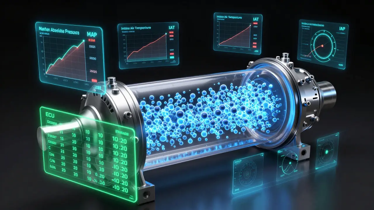
Speed Density tuning takes a completely different approach. Instead of measuring the air directly, it calculates the mass of air by looking at the conditions inside the intake manifold. It uses three main inputs: Manifold Absolute Pressure (MAP), Intake Air Temperature (IAT), and Engine Speed (RPM).
The ECU knows the volume of the intake ports and cylinders. By knowing the pressure (density) and temperature of the air in those spaces, and how fast the engine is spinning (speed), it can calculate exactly how much air is trapped in the cylinders using the ideal gas law. It’s essentially physics-based estimation rather than direct measurement.
This method requires a robust Engine Control Unit (ECU) capable of handling complex multi-dimensional tables. You’ll spend your tuning time adjusting Volumetric Efficiency (VE) tables rather than smoothing out MAF curves. VE represents how well the engine breathes at various RPMs and loads. A naturally aspirated engine might hit 85% VE, while a highly tuned forced-induction setup could exceed 100% due to positive pressure forcing air in.
Why do professional tuners love this? Because the sensors involved-MAP and IAT-are not in the direct path of airflow. They sit in the manifold, protected from debris. They rarely fail, they don’t get dirty, and they provide consistent readings even after years of hard driving. For drag racers or track day warriors who change turbos, intercoolers, and intake manifolds constantly, Speed Density is a lifesaver. You swap hardware, and the ECU still knows what’s happening because it’s monitoring pressure, not flow rate.
Key Differences: Sensors, Reliability, and Response
When choosing between these strategies, you aren’t just picking a tuning style; you’re selecting a hardware ecosystem. The differences extend beyond the ECU software into the physical components bolted to your engine.
| Feature | MAF Tuning | Speed Density Tuning |
|---|---|---|
| Primary Sensor | Mass Air Flow Sensor | Manifold Absolute Pressure (MAP) + IAT |
| Sensor Location | Intake Tube (exposed to airflow) | Intake Manifold (protected) |
| Tuning Complexity | Lower (Linear curve adjustment) | Higher (Multi-dimensional VE tables) |
| Hardware Swaps | Requires recalibration for new intakes/turbos | Minimal adjustment needed |
| Idle Quality | Can be unstable if sensor is contaminated | Generally smoother and more stable |
| Cost | Cheaper sensors, simpler wiring | Higher quality MAP/IAT sensors recommended |
One critical advantage of Speed Density is its ability to handle variable valve timing (VVT) and cam changes more gracefully. Since VE tables account for how much air actually enters the cylinder, changing cams simply alters the shape of the VE map. With MAF, a significant change in airflow characteristics can render the old calibration useless, requiring a full re-map from scratch.
However, Speed Density isn’t magic. It relies heavily on accurate engine speed and pressure data. If your crank position sensor is noisy or your MAP sensor is cheap and slow-reacting, your calculations will be off. That’s why high-end setups often use dual MAP sensors-one for general tuning and another specifically for wide-open throttle accuracy-to ensure the ECU doesn’t lean out under boost.
Which Strategy Fits Your Build?
There is no single "best" option, only the best option for your specific goals. Let’s look at real-world scenarios to help you decide.
Stick with MAF if:
- You drive a stock or mildly modified daily driver. The factory calibration is likely optimized for emissions and fuel economy using MAF data.
- Your budget is tight. MAF sensors are generally cheaper to replace than high-precision wideband oxygen sensors and premium MAP sensors often paired with SD tunes.
- You use an entry-level standalone ECU that lacks the processing power for complex VE table tuning. Many basic ECUs default to MAF because it’s easier to implement.
Switch to Speed Density if:
- You run forced induction (turbo or supercharger). Boost pressure fluctuates rapidly, and MAF sensors can lag behind these changes, causing transient lean spikes that destroy engines. MAP sensors react instantly to pressure changes.
- You frequently change intake components. Swapping a turbo manifold or upgrading your intercooler piping changes airflow dynamics. With Speed Density, you adjust the VE table. With MAF, you might need a new sensor or extensive re-calibration.
- You race. Consistency is king. You don’t want your tune to drift because the MAF got hot or dusty during a long endurance event. Speed Density provides rock-solid reliability under extreme conditions.
- You have a flat-six or V-engine configuration. These engines often have uneven airflow distribution between banks. A single MAF sensor sees total air, but doesn’t know how it splits. Speed Density, combined with bank-specific O2 sensors, allows for finer control over each side of the engine.
Common Pitfalls and How to Avoid Them
Even with the right strategy, mistakes happen. Here are the most common issues tuners face when navigating MAF vs. Speed Density territory.
The "Lean Spike" Problem: In turbocharged cars, when you lift off the throttle, boost dumps quickly. A MAF sensor reacts slowly to this drop in airflow, so the ECU continues injecting fuel based on the previous high-airflow reading. When you stomp back on the gas, the MAF hasn’t caught up yet, causing a momentary lean condition. Speed Density avoids this because MAP sensors see the pressure drop instantly. If you stay on MAF, you must program aggressive transient fuel correction tables to compensate.
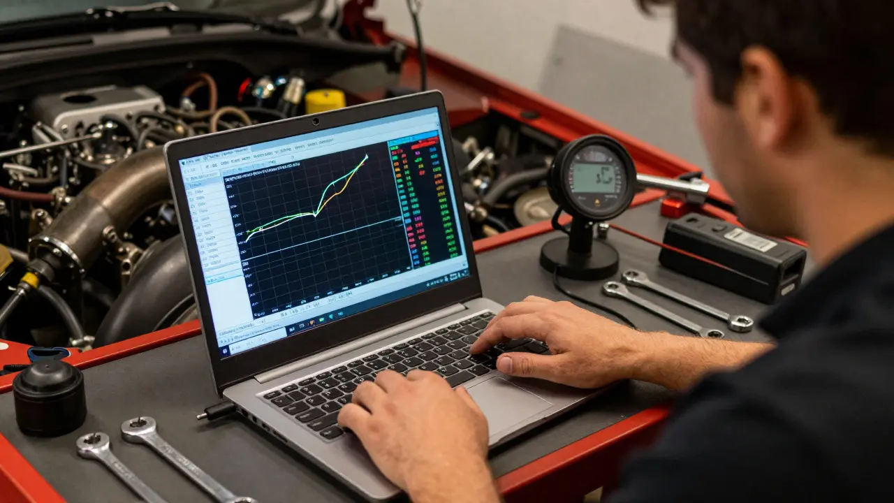
Incorrect VE Tables: New to Speed Density? Don’t copy someone else’s VE table. Every engine has unique breathing characteristics based on port shape, cam profile, and head design. Start with a conservative estimate (like 60-70% VE) and use a wideband oxygen sensor to dial it in. Lean is dangerous; rich is safe but wasteful. Always err on the rich side until you have precise data.
Ignoring Barometric Pressure: Both systems need to know atmospheric pressure to function correctly. If you live in a valley and drive to the mountains, air density drops. MAF systems usually have a built-in barometric compensation feature. Speed Density systems rely on the MAP sensor to detect ambient pressure at idle. Ensure your ECU’s barometric compensation settings are enabled, or your tune will go lean at altitude.
Future-Proofing Your Engine Management
As we move further into 2026, modern ECUs are becoming incredibly powerful. Many now support hybrid approaches, using both MAF and MAP data simultaneously. This redundancy allows the ECU to cross-check readings. If the MAF says 10g/s but the MAP calculation suggests 12g/s, the ECU can flag a fault or average the data for better accuracy.
If you’re installing a new standalone ECU today, choose one that supports Speed Density natively. Even if you start with MAF, having the capability to switch later saves money and hassle. Look for features like multiple MAP sensor inputs, advanced transient fueling algorithms, and user-friendly VE table editing tools. Brands like MoTeC, Haltech, and Link Engineering lead this space, offering robust platforms that grow with your build.
Remember, tuning is iterative. Whether you choose MAF or Speed Density, the goal is the same: precise fuel delivery for maximum power and reliability. Understand your engine’s needs, pick the right tool, and always verify your data with a wideband oxygen sensor. Your engine will thank you.
Can I convert my MAF-only ECU to Speed Density?
It depends on your ECU. Most modern standalone ECUs support both modes via software switches. Older or cheaper ECUs may be hardware-limited to MAF only. Check your ECU’s manual or manufacturer specifications. If conversion is possible, you’ll also need to install a MAP sensor and potentially an Intake Air Temperature (IAT) sensor if your current setup doesn’t have one in the manifold.
Is Speed Density tuning harder than MAF tuning?
Yes, initially. MAF tuning involves adjusting a single linear curve. Speed Density requires filling out multi-dimensional Volumetric Efficiency (VE) tables across RPM and load axes. However, once dialed in, Speed Density is more forgiving of hardware changes and offers better transient response. There is a steeper learning curve, but the payoff in reliability and performance is significant for modified engines.
Do I need a wideband oxygen sensor for Speed Density tuning?
Absolutely. While closed-loop fuel control can help at cruise, wideband O2 sensors are essential for verifying your VE tables under load. Since Speed Density is calculated, not measured, you need real-time feedback to ensure your calculations match reality. Without a wideband, you’re guessing, which can lead to lean conditions and engine damage.
Why does my MAF sensor give inconsistent readings?
Contamination is the usual culprit. Oil from PCV systems, silicone spray from cleaners, or dust buildup can coat the sensing element. Clean the sensor with specialized MAF cleaner (not brake cleaner or carburetor cleaner). Also, check for air leaks before the MAF sensor. Unmetered air entering after the sensor causes lean codes because the ECU doesn’t know that extra air exists.
Can I use both MAF and MAP sensors together?
Yes, many advanced ECUs allow hybrid operation. The ECU can use MAF for baseline airflow and MAP for boost verification and transient corrections. This setup provides redundancy and improved accuracy. However, it adds complexity to the tune. Ensure your ECU firmware supports dual-sensor fusion logic to avoid conflicting data signals.