
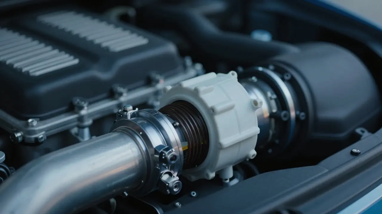
Picture this: you’re sitting in your car, foot on the gas, and the engine hesitates. It stumbles. That split-second delay between pressing the pedal and feeling the power is often a symptom of how your engine knows how much air it’s breathing. This isn’t just about horsepower; it’s about communication. Specifically, it’s about the battle between two dominant methods of measuring airflow: Mass Air Flow (MAF) sensors and Speed Density systems.
If you are tuning an engine, whether for daily driving or track use, understanding the difference between these two strategies is non-negotiable. One relies on a direct measurement of air mass entering the intake manifold, while the other calculates that value based on manifold pressure and engine speed. Getting this wrong can lead to lean conditions, poor throttle response, or even catastrophic engine failure. Let’s break down exactly how they work, where they fail, and which one actually serves your specific build better.
The Core Difference: Measuring vs. Calculating
To understand why tuners argue over MAF versus Speed Density, you first need to grasp what each system is trying to tell the Engine Control Unit (ECU). The ECU needs to know precisely how much oxygen is entering the combustion chamber so it can inject the correct amount of fuel. Too little fuel causes a lean condition (hot, dangerous); too much causes a rich condition (wasted fuel, fouled plugs).
Mass Air Flow (MAF) sensors measure the actual mass of air flowing past a heated wire or film inside the intake pipe. As air flows over the sensor, it cools the element, and the ECU increases electrical current to maintain temperature. The amount of current required correlates directly to the mass of air. It is a direct measurement. If the air moves, the MAF sees it.
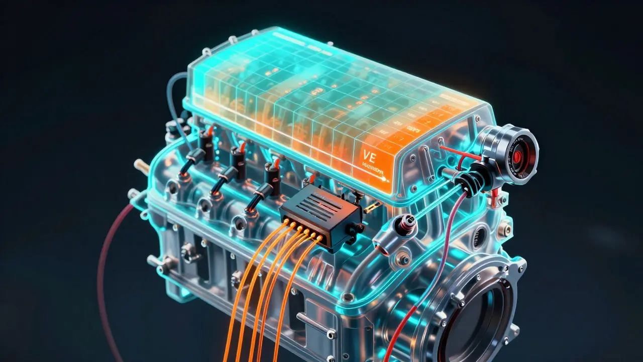
In contrast, Speed Density tuning does not measure air flow directly. Instead, it uses a combination of inputs-primarily Manifold Absolute Pressure (MAP) sensor data, engine RPM, and Intake Air Temperature (IAT)-to calculate the volume of air in the cylinders. The ECU applies a volumetric efficiency (VE) table to estimate how full the cylinders are at any given moment. It is an estimation model, refined by feedback from the oxygen sensors.
The fundamental distinction here is reliability under changing conditions. A MAF sensor tells the ECU "this much air entered." Speed Density tells the ECU "based on pressure and speed, this much air *should* be there."
How MAF Sensors Work and Where They Struggle
MAF systems have been the standard for naturally aspirated street cars since the late 1980s because they are relatively easy to implement and provide immediate accuracy across the entire operating range. However, they come with significant physical limitations.
The biggest enemy of a MAF sensor is contamination. Because the sensing element sits directly in the airstream, it collects oil vapor from crankcase ventilation, dust, and dirt. Over time, this buildup insulates the heating element, causing the sensor to report lower airflow than is actually present. The result? A lean mixture. You might notice hesitation during acceleration or a check engine light for "System Too Lean."
Furthermore, MAF sensors struggle with high-flow applications. If you install a massive cold air intake or upgrade to large turbochargers, the velocity of the air changes. MAF sensors rely on consistent airflow velocity profiles. Turbulent air from poorly designed intakes can confuse the sensor, leading to erratic readings. In extreme high-RPM scenarios, the sheer volume of air can exceed the sensor's calibration range, causing the ECU to default to a limp mode or unsafe fuel maps.
For tuners, working with MAF requires careful attention to signal conditioning. You must ensure the wiring harness is clean, the connector is secure, and the sensor itself is pristine. Unlike MAP sensors, which are sealed inside the manifold, MAF sensors are exposed to the elements right behind the air filter.
The Logic Behind Speed Density Systems
Speed Density became popular in performance circles because it removes the single point of failure associated with MAF sensors. By relying on the MAP sensor, which measures static pressure in the intake manifold, the system is less susceptible to external contaminants. The MAP sensor is typically located deep within the engine bay, protected from road debris and oil mist.
The core of Speed Density tuning is the Volumetric Efficiency (VE) table. This is a grid in the ECU that defines how efficiently the engine fills its cylinders at various RPMs and load levels. For example, at idle, VE might be 15%. At peak torque, it could hit 95% or higher with forced induction. Tuners spend hours logging data to populate this table accurately. They drive the car through various loads, watch the wideband oxygen sensor feedback, and adjust the VE cells until the calculated air matches the actual air.
This method shines in forced induction applications. Turbocharged engines experience rapid changes in boost pressure. A MAF sensor can lag slightly as it reacts to sudden spikes in airflow. A Speed Density system, however, reacts instantly to pressure changes. When the turbo spools, the MAP sensor sees the pressure rise immediately, allowing the ECU to add fuel proactively rather than reactively.
Additionally, Speed Density allows for more precise control over closed-loop operation. Since the system is constantly comparing its calculated air values against real-time oxygen sensor data, it can self-correct minor discrepancies in the VE table automatically. This makes it highly adaptable to wear and tear over the life of the engine.
Comparing Performance and Reliability
| Feature | MAF Tuning | Speed Density Tuning |
|---|---|---|
| Measurement Type | Direct Mass Measurement | Calculated Volume (Pressure + RPM) |
| Sensor Location | Intake Pipe (Exposed) | Intake Manifold (Protected) |
| Tuning Complexity | Low (Linear Scaling) | High (VE Table Mapping) |
| Response Time | Moderate (Thermal Lag) | Fast (Instant Pressure Read) |
| Fault Tolerance | Low (Single Point Failure) | High (Redundant Inputs) |
| Ideal Application | Naturally Aspirated Stock Engines | Turbo/Supercharged & High-Performance |
When looking at the table above, the trade-offs become clear. MAF is simpler to tune initially. You don’t need to map a complex VE table; you just scale the MAF voltage to airflow ratio. However, it is fragile. If the sensor fails, the engine runs poorly or not at all. Speed Density requires more upfront effort to tune correctly, but once dialed in, it is robust. It handles vacuum leaks differently too. In MAF systems, a vacuum leak after the sensor introduces unmetered air, causing a lean condition. In Speed Density, the MAP sensor detects the drop in manifold pressure caused by the leak, allowing the ECU to compensate partially.
Choosing the Right Strategy for Your Build
So, which one should you choose? It depends entirely on your goals and your engine configuration.
If you are running a stock or mildly modified naturally aspirated engine, sticking with MAF is often the best choice. The factory calibrations are already optimized for this setup. Adding a larger MAF sensor if you increase displacement is straightforward. You avoid the complexity of VE mapping and benefit from the simplicity of direct measurement. Most modern ECUs handle MAF signals very well, provided the sensor is kept clean.
However, if you are adding forced induction-a turbocharger or supercharger-Speed Density is generally superior. The dynamic nature of boost pressure makes calculated airflow more responsive. Moreover, many high-performance ECUs allow you to run both systems simultaneously. This hybrid approach uses MAF for baseline accuracy and Speed Density for transient response and redundancy. If the MAF signal drops out, the ECU seamlessly switches to Speed Density using the VE table, keeping the car drivable.
For drag racers or track enthusiasts who push engines to their limits, Speed Density offers greater precision at high RPMs. MAF sensors can become inaccurate when airflow becomes supersonic or highly turbulent in the intake tract. Speed Density, relying on cylinder filling efficiency, remains stable as long as the VE table is accurate.
Troubleshooting Common Issues
Even with the right strategy, problems arise. Here is how to diagnose common failures.
- Hesitation on Acceleration: If you switch to Speed Density and experience hesitation, your VE table may be too low in the transition areas. Check your wideband logs for short-term fuel trims. If they are positive, you are running lean; increase the VE cells.
- Rough Idle: In MAF systems, a dirty sensor is the usual culprit. Clean it with specialized MAF cleaner. In Speed Density, check for vacuum leaks around the intake manifold gaskets. The MAP sensor will read incorrect pressure if air is bypassing the throttle body.
- Limp Mode Activation: Both systems can trigger limp mode if sensor ranges are exceeded. For MAF, ensure the maximum voltage output doesn't exceed the ECU's limit. For Speed Density, verify that your MAP sensor rating matches your boost levels. A 1-bar MAP sensor on a 2-bar turbo setup will max out and lose accuracy.
Always log data. Without a wideband oxygen sensor and a data logger, you are guessing. Whether you use MAF or Speed Density, real-time feedback is the only way to validate your tuning decisions.
Future Trends in Airflow Management
As engine technology evolves, we are seeing a shift toward multi-point sensing. Modern ECUs are beginning to integrate multiple MAP sensors-one before the throttle and one after-to account for throttle position dynamics more accurately. Additionally, machine learning algorithms in next-generation ECUs promise to auto-tune VE tables based on driving patterns, reducing the manual labor involved in Speed Density calibration.
Nevertheless, the physics remain unchanged. Air must be measured or estimated. Understanding the strengths and weaknesses of MAF and Speed Density ensures your engine breathes efficiently, safely, and powerfully. Choose wisely, tune carefully, and always trust your data.
Can I convert my MAF car to Speed Density?
Yes, but it requires hardware and software changes. You need a compatible MAP sensor installed in the intake manifold, and your ECU must support Speed Density mode. Many aftermarket ECUs allow you to disable the MAF input and enable Speed Density via software settings. Once enabled, you will need to build a new VE table from scratch using a wideband oxygen sensor and data logging tools.
Which system is better for turbocharged engines?
Speed Density is generally preferred for turbocharged engines. It responds faster to boost pressure changes and is less prone to errors caused by turbulent airflow from large intercoolers or piping. The ability to predict airflow based on pressure allows for more precise fuel delivery during rapid throttle transitions, improving both performance and safety.
What causes a MAF sensor to fail?
The most common cause is contamination from oil vapors, dust, or silicone sprays used incorrectly near the intake. Physical damage from dropping the sensor or electrical issues like corroded connectors can also cause failure. Symptoms include rough idling, poor acceleration, and increased fuel consumption.
Do I need a wideband oxygen sensor for Speed Density tuning?
While not strictly mandatory for basic operation, a wideband oxygen sensor is essential for accurate tuning. Since Speed Density relies on calculations, you need real-world feedback to verify that your VE table is correct. The wideband provides precise Air-Fuel Ratio (AFR) data, allowing you to adjust the VE cells until the engine runs optimally across all RPM and load conditions.
Can I run both MAF and Speed Density simultaneously?
Yes, many advanced ECUs support hybrid tuning. In this setup, the ECU uses MAF data for primary fuel calculation and Speed Density for secondary validation or transient response. This provides redundancy; if the MAF sensor fails, the ECU can fall back to the Speed Density VE table, preventing engine stall or severe running issues.